
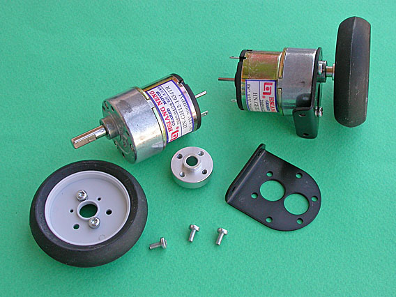
COMPONENTS REQUIRED:
4 DC geared motors with wheels and motor connecting clamps.
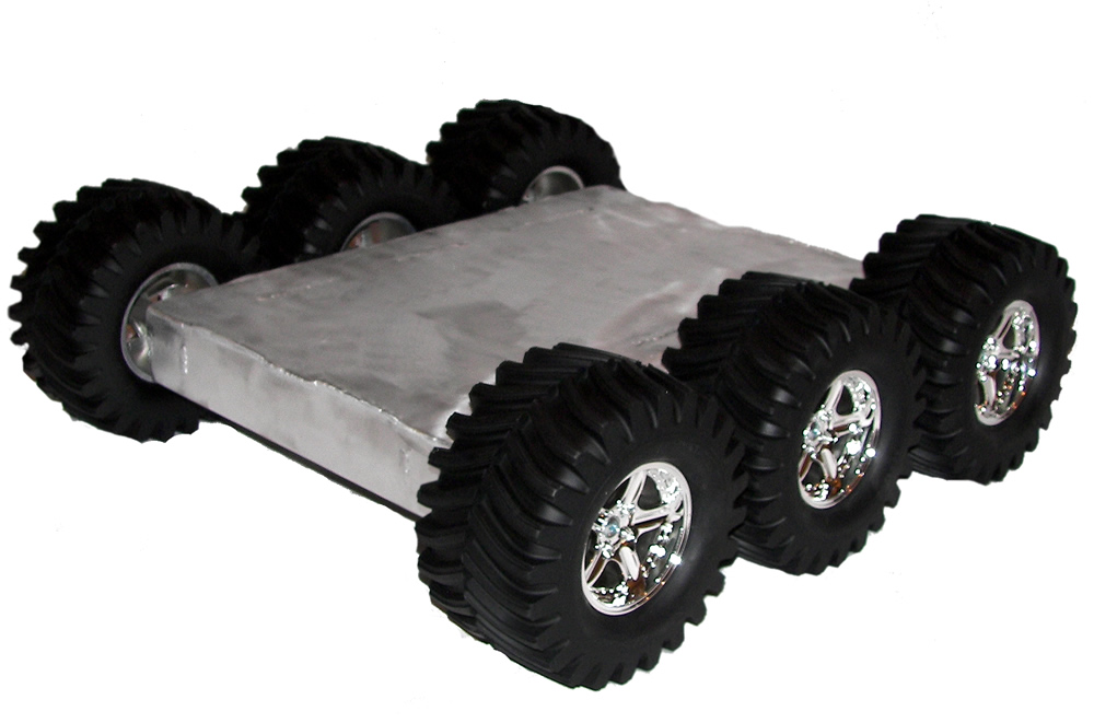
Robot base.
Voltage regulator IC 7805.
9 V battery with battery connector.
Bread board or PCB (the one you are most comfortable with).
IR sensors – 2 no (one for left and one for right).
Motor driver L293D.-->
PROCEDURE:
--> - Fix the motors on the base and fix the wheels to the motors.
--> 2.Fix the sensors in such a manner that the IR transmitter and receiver face the floor (so that they can detect the black line) with a clearance of 3 to 5 mm.


-->3.You will have three pins for each sensor. One is supply, one ground and the third one is for output data.

-->4.Connect the grounds of the sensors and the ICs and also the negative of the battery at the same terminal.
-->5.Connect the positive of the battery to the supply pins of the sensors and also the motor driver IC (take care that the input to the motor driver at any point of time should not be greater than 5V. This is achieved using the voltage regulator IC. Thus, the input supply to the motor driver comes from the output pin of the voltage regulator).


-->

-->
The test track should be made in such a way that the width of the line you draw must be lesser than the spacing between the sensors by at least 5 mm for smooth running of the bot.
No comments:
Post a Comment